the guideline to soldering mainboards    Page No.:A31


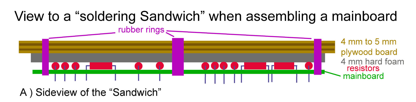
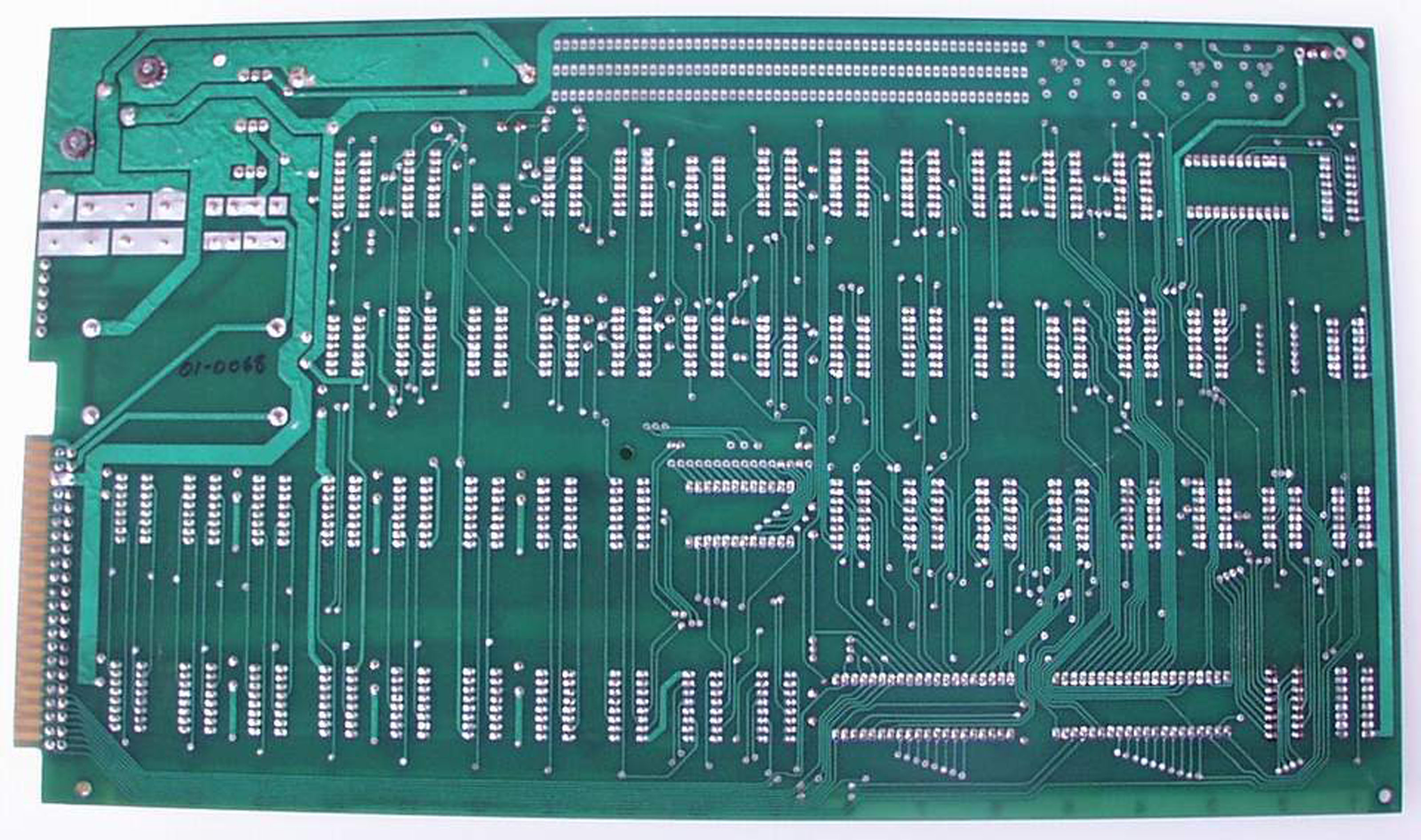
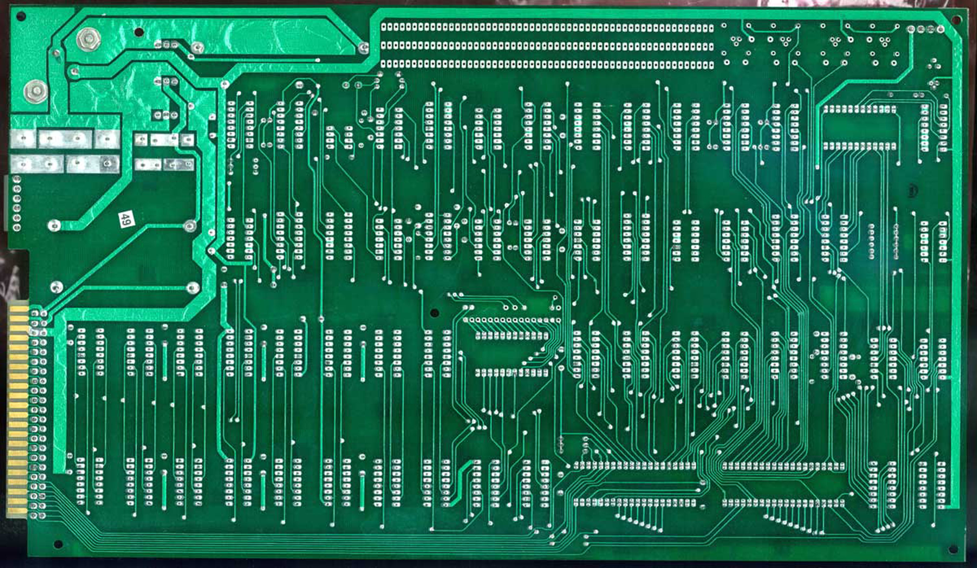
Soldering a mainboard can become a frustrating and horrible task if some tips are not performed and the results might even leed up to a
 nonfunctional mainboard. If the mainboard is not assembled in a professional factory with wavesoldering bath then there are several
 problems to handle in the most important one is that you would need a few hands more than you can offer.
 But there is a simple solution : working with the "Sandwich" - method.
 the assembly is split to several different stages - depending to the "hight" of the components....
 in general a Mimeo boards for example will be split to the following groups / steps:
 1) resistors
 2) sockets
 3) filter capacitors and ceramic capacitors
 4) small electrolytic capacitors and crystal
 5) edgeconnector
 6) transistors
 7 ) voltage ICīs and connectors
 8)  finally the big electrolytic capacitors and the volatgeregulator with the cooling sink

 First of all you will need to get a peice of stabile plywood with about 4 mm or 5 mm thickness and the size should be only little bit larger than
 the Mimeo mainboard itself ( there should be a border of 1 cm more at each side of the mainboard ). That board should be very stiff !
 You should not be able to bend it ! This plywood board should then be covered completely at one side with a rather hard ( only little flexibel )
 foam that is not to weak against heat ( no styrofoam !) by fixing it to the wood with sheets of doubleside- adhesive tape.
 
 In the first step all resistors are inserted in the board and then the plywood board is placed on the top above the resistors and then that plywood board is 
 fixed with large and strong rubber rings like shown in the drawing below.


 When the "Sandwich" is complete and the rubber rings are strong enough, then you can flip that entire "package" around and start to solder the resistors.
 After that Task has been completed you can flip back the package and remove the rubber rings. You may then start equipping the mainboard with all sockets
 and then you may prepare the "Sandwich" same way as before and fix the package again with the rubber rings.

  Tip: If you first only solder one side of the resistors so that they keep in position then you may start cutting the remaining unsoldered wires that way, that
           the rest of wire just keeps about 1 mm above the surface of the board and then solder that remaining points. Then you can cut the remaining soldered
           wires as short as possible.


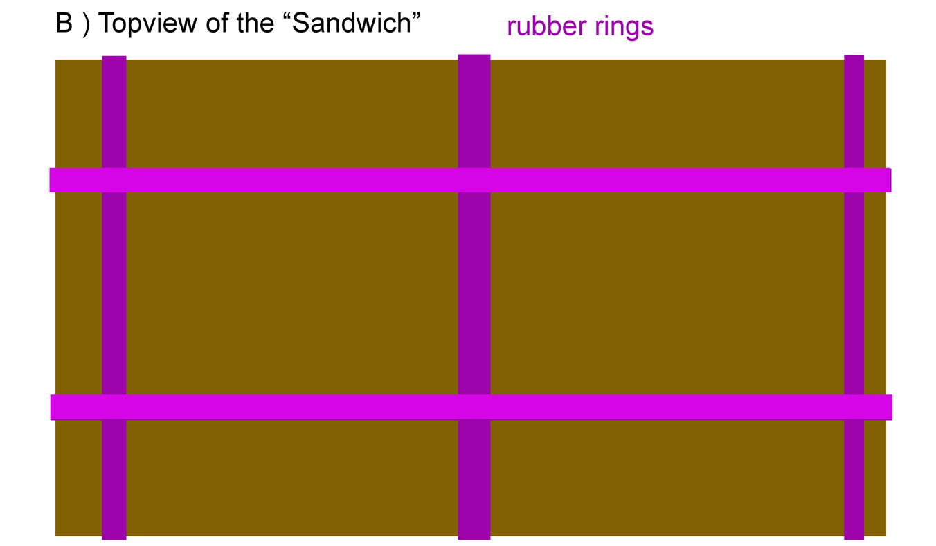
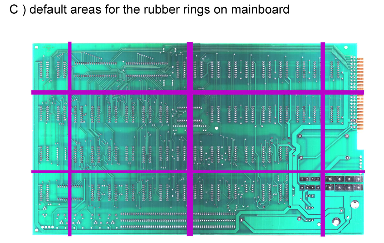
 The rubber rings should be positioned like displayed in the picture above to make sure that the pressure of the rings is supplied equaly to the entire surface
 of the mainboard at the other side of the package.
 That also is corresponding to the areas at the mainboard where nearly  no soldering points are used.


 When the "Sandwich" is prepared with the sockets you may flip the package again to prepare the soldering task
 But you should not solder the entire socket at the moment ! Itīs better to only solder 2 pins of the opposing edges  like marked in the 2 pictures below
 ( the second one id only a detail of the picture above ).


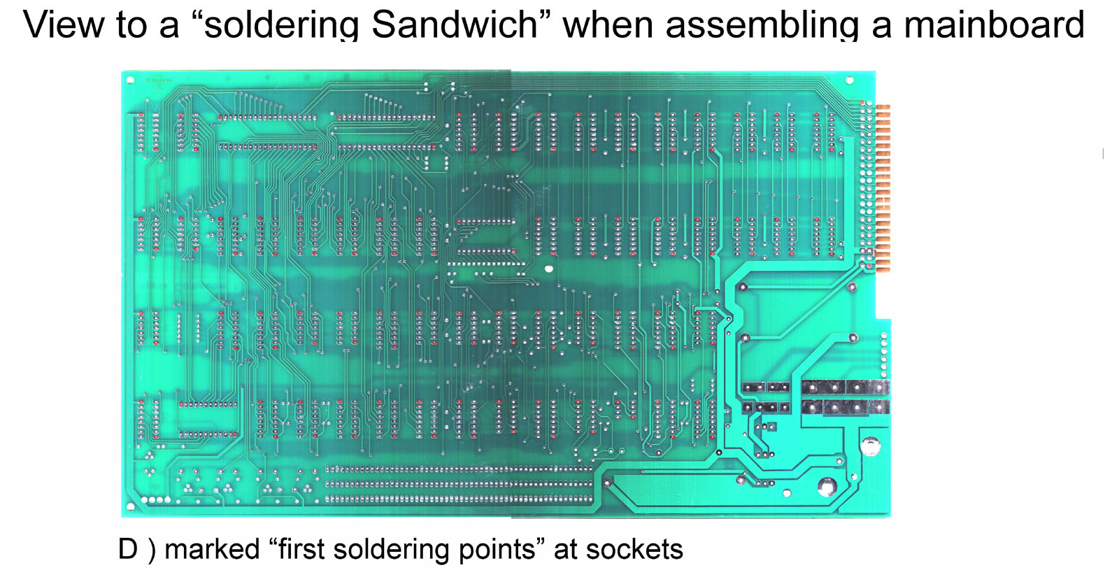
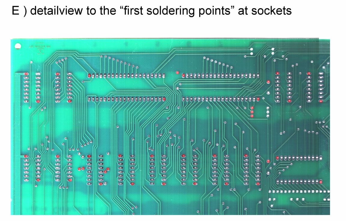
 After all sockets have been fixed at 2 points you may remove the rubber rings and the plywoodboard. Then you should heat again the soldering joints
 with the solderingiron each single after another while pressing the socket with a fintertip at the other side down to the mainboard. This will ensure that the socket will
 slip down the very last few parts of a millimeter in their final position. After all joints have been readjusted you may solder all the remaining unsoldered
 points of the sockets.

 After the task with the sockets is completed the same procedure is repeated again as listed above with the next "higher" components.
 
 The next pictures examine details related to "good" and "bad" soldering joints. But before we examine that pictures, it is very important to
 remind, that the results of soldering are also dependent to the quality of the used tools. You wonīt get good results with bad tools and bad
 soldering material. This is upmost valid, if you want to solder an entire mainboard ! In such a case it is mandatory the you must use a soldering
 iron with temperature regulation. The tip of  a soldering iron without temperature regulation is completely oxidated after some 50 to 60 soldering joints
 and the oxidated particals on the tip cause bad effects to the solderingmaterial. It will oxidate faster and the flux of the material gets worser the more
 the tip is oxidated. Using a soldering iron with partialy ceramic tip and regulation fixed to 300 to 350 degrees celsius makes sure that the solderingmaterial
 has best flux and the tip canīt oxidate at that temperature.
 Donīt use e large soldering tip ! The correct tip is the one salled in general as "pencil tip" and it comparable to the size of a normal pencil.
 The soldering unit should be able to deliver regulated power from 15 Watt to 50 Watt and it should be able to be regulated from 250 degrees celsius
 till up to 450 degrees celsius. The optimal soldering temperature is between 340 degrees and 360 degrees celsius and the soldering material shold
 have a diameter from 0,4 mm to maximum of 1 mm. Using thicker material causes danger of applying to much material to the soldering area.
 The pictures below show the difference by displaying how a good soldering joint should look alike.
 The picture of the bad soldering joint shows 2 points: the soldering material was too cold and  did not get really good flux and therefor it also could not "creep"
 into the hole and float entirely around the wire. The picture H) displays very well a perfect joint: the joint looks similar to the profile  of a "volcano".
 In a later step the remaining part of the socket pins above the soldering material are cut off with a good and sharp wirecutter.


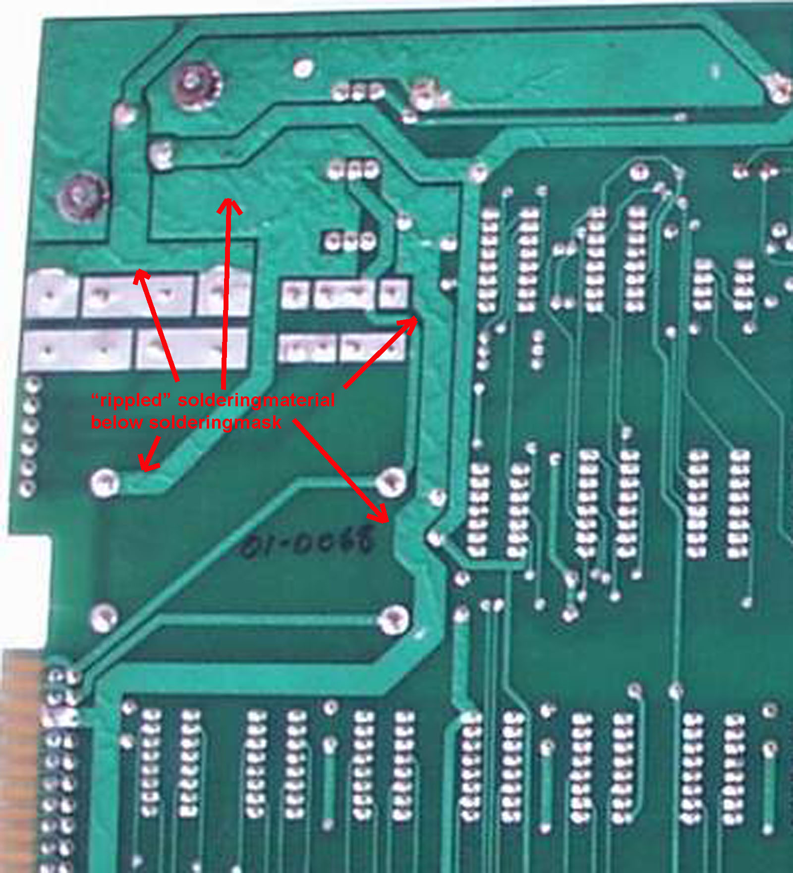
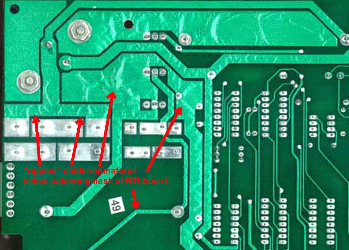
  At Applefritter the member PhilPower mentioned correctly that nobody will be able to reproduce perfectly the solderingside of an Apple 1 and this is the best statement to be
  given about the topic. This has mechanical reasons due to the fact that the original board had been wavesoldered. i will display this with some few detail pictures:


       The pictures above have been from "pre NTI" version
  of the Apple-1. Even at the "NTI" version of the Apple
  this remarkable evidence from wavesoldering can
  be viewed well - as seen in the rightsided picture from
  the soldering side of an original NTI-version of the board.

  For those who want still to view a hirespicture i have added
  here a link to the entire preNTI version and the NTIversion.

  Below i display the details from a MIMEO-board scan and a
  picture from a Newton NTI- board aafter the sockets only had
  been soldered. Itīs easyto recognize the differences when
  viewing the traces below the green soldermask.
        Scan from part of  the MIMEO board just right after delivery  Partial picture taken from Newton NTI board just after soldering the sockets


  So the final conclusion will be, that we can only at least make as perfect as possible reliable soldering joints with few soldering material as possible
  - but as much material as required to result to reliable soldering joints......


       due to european laws and german court decision:
 I hereby declare no responsibility to any "deep links" resulting from the links in this page. I have no influence to the pages linked hereby in this page and the
 contents in those pages. I therefor canīt take any kind of responsibility to contents in the pages, where these links direct the readers browser to nor to the
 contents resulting from following up links from those pages. The reference to contents by this links is dependent ro the status of the date when the links have
 been set ( April 2013 ) and it might occur that references and contents may change by the fact that domains may have been discontinued from their former owners.
 In such cases i canīt take any kind of responsibility to the changed contents. this is specialy valid to banners, advertisements or merchandising links in the targeted
 pages.